Marine Radar FAR-21x7, FAR-28x7


FEATURES:
-
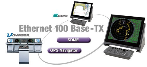
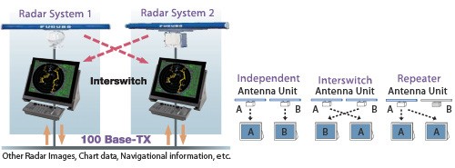
100 Base-TX Ethernet Network System
The 100 Base-TX Ethernet is utilized to network up to four sets of FAR-21x7/28x7 series radar with ECDIS FEA-2107/2807. This Ethernet data link gives high-speed and stable navigational data sharing amongst the equipment networked within the system. This network capability gives options to choose from a single station system configuration to complete Integrated Navigation System (INS).
-
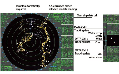
Target Tracking(TT: ARPA)/AIS
The FAR-21x7/28x7 series radar delivers full TT functionality and can plot up to 100 targets. In addition, this radar series is displaying up to 1,000 targets received from the AIS transponder system. Detailed information about the targets can be shown in data cells on right hand side of the screen. TT/AIS information Scheme gives the operator full control over dense traffic. The type of AIS Symbol shows if it is a sleeping target, a normal target, a selected target, a dangerous target or a lost target.
-
AIS Symbols
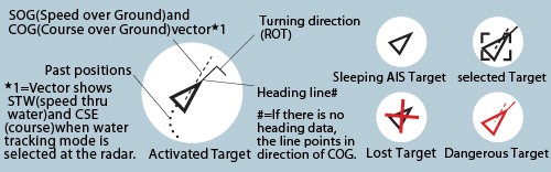
COG/SOG vector changes its length with speed. ROT mark is viewable at the COG/SOG vector tip when a target has FURUNO Satellite Compass SC-50/110 or gyrocompass, which deal ROT serial sentence, installed.
-
Automatic Acquisition Zones
Two automatic acquisition zones can be set in a sector or in any form. These zone act as suppression zones, avoiding unnecessary overloading to the processor and clutter by disabling automatic acquisition and tracking outside them. Targets in an automatic acquisition zone are shown with an inverse triangle. The operator can manually acquire important targets without restriction, an essential aid and source of information on assessing the situation.
-
Guard Zones and Anchor Watch Zone
Guard Zones generate visual and audible alarms when targets entered the operator-set zones. One of the Guard Zones can be used as an anchor watch to alert the operator when own ship or targets drift away from the set zone.
-
CPA Alarm
The target tracking symbol changes to a triangle when its predicted course violates the operator-set CPA/TCPA so that the operator may be notified of the approaching targets to the own ship for collision avoidance. The operator can readily change the vector lengths to evaluate the target movement trend.
-
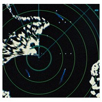
Target Trails
Target trail feature generates a monotone or gradual shading afterglow on all objects on the display in order to help clarify traffic situation.
-
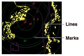
Radar Map
A radar map is a combination of lines and marks whereby the operators can define and input the navigation area and route planning/monitoring data. The radar map can include up to 20,000 points for lines and marks.
-
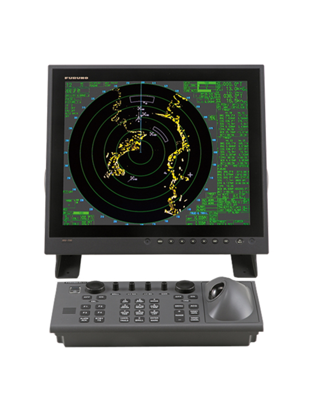
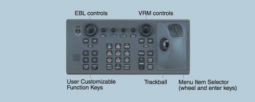
Stress-free Operation through Ergonomically-designed Control Unit
The control head has logically arranged operation Scheme through a combination of push keys and a trackball. Well-organized menus ensure that all operations can be performed with a trackball.
Full-keyboard control head
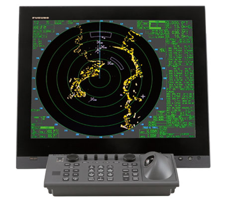
Trackball control head
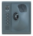
Alternative to the Full-keyboard type or additional control head to be placed close to captain chair for remote operation.
SPECIFICATIONS:
|
ANTENNA RADIATORS |
|
| Type |
Slotted waveguide array |
| Polarization |
Horizontal |
| Rotation |
FAR-2117/2117-BB/2127/2127-BB/2827: 24 rpm or 42 rpm FAR-2157/2157-BB: RSB-106, 18 rpm (50 Hz)/22 rpm (60 Hz),RSB-107, 22 rpm |
|
RF TRANSCEIVER |
|
| Frequency |
X-band: 9410 MHz ±30 MHz, S-band: 3050 MHz ±30 MHz 2. |
| Output power |
FAR-2117/2117-BB/2817: 12 kW |
| DISPLAY UNIT | ||
| Screen | Yellow or green echoes in 32 levels. Rasterscan non-interlace at 64 |
|
| FAR-21x7 series | FAR-28x7 series | |
| Size, model | 20.1-inch color LCD, MU-201CR | 23.1-inch color LCD, MU-231CR |
| Display area (mm) | 399.36 x 319.49 | 470.4 x 352.8 |
| Resolution | 1280 x 1024 pixels | 1600 x 1200 pixels |
| Effective radar diameter | 308 mm (H: 64 kHz, V: 60 Hz) |
340 mm (H: 75 kHz, V: 60 Hz) |
| Minimum range and range discrimination | Minimum range: 20 m w/raw video + 0-2 m w/digitize error Range discrimination: 20 m w/raw video + 0-6 m w/digitize error |
|
| Range scales (nm), ring interval |
0.125 (.025), 0.25 (0.05), 0.5 (0.1), 0.75 (0.25), 1 (0.25)*, 1.5 (0.25), 2 (0.5)*, 3 (0.5), 4 (1)*, 6 (1), 8 (2)*, 12 (2), 16 (4)*, 24 (4), 32 (8)*, 48 (8), 96 (16), 120 (20)* |
|
| Range accuracy | Within 1% |
|
| Bearing discrimination |
0.95° (XN4A), 0.75° (XN5A), 2.1° (XN12AF), 1.5° (XN20AF), 1.2° (XN24AF), 2.5° (SN30AF), 2.0° (SN36AF) |
|
| Bearing accuracy | ±1° | |
| Presentation mode |
Head-up, Head-up TB, North-up, Course-up, True Motion sea or ground stabilization |
|
| Plotting facilities (ARPA or ATA) | Auto or Manual acquisition: 100 targets in 0.1-32 nm Auto tracking on all acquired targets | |
| Radar map | Nav lines, coastlines, buoys, etc. produced by operator. 20,000 pts in radar mode, 6000 pts on IC card in chart mode | |
| Guard zone | GZ1: 0.5 nm width sector, within 3-6 nm, desired bearing GZ2: 1 nm width sector or polygon, desired range and bearing |
|
| Parallel index line | Choice of 2, 4 or 6 lines | |
| AIS | IMO SN Circ.217, IEC/PAS 60936-5 | |
| Chart cards | FURUNO and NAVIONICS | |
| INTERFACE | |
| IEC 61162-1 Ed. 2 | RSD, TTM, AIS related data, etc. |
| Compass | Built-in interface (option) for sync signal (20-135 V, 50-400 Hz), or stepper signal (20-135 VDC), any polarity, for gyrocompass, GPS compass SC-60/120 by IEC 61162-2 |
| Speed log | NMEA format data |
| Others | Echo sounder, GPS navigator, water temperature, etc. |
| PERFORMANCE MONITOR | |
| PM-31 (X-band) | |
| Frequency range | 9365 to 9455 MHz |
| Input power | Min. +8 dBm, Max. +28 dBm |
| Power output (2nd pulse max output) | -36 dBm |
| Power output (2nd pulse min output) | -56 dBm |
| Steps levels (1st pulse to 2nd pulse) | .0 to 11.0 dB |
| PM-51 (S-band) | |
| Frequency range | 3020 to 3080 MHz |
| Input power | Min. -5 dBm, Max. +15 dBm |
| Power output (2nd pulse max output) | -15 dBm |
| Power output (2nd pulse min output) | -35 dBm |
| Steps levels (1st pulse to 2nd pulse) | 9.0 to 11.0 dB |
| POWER SUPPLY | ||||||||||||||||||||||||||
| Display unit | 24 VDC or 115/230 VAC, 1ø, 50/60 Hz FAR-21x7: 24 VDC, 2.3 A; 100-230 VAC, 0.7A (100 V) FAR-28x7: 24 VDC, 3.2 A; 100-230 VAC, 0.9 A (100 V) 440 VAC, 1 ø, 50/60 Hz with optional transformer RU- 1803 2. |
|||||||||||||||||||||||||
| Processor unit | FAR-2117/2817/2117-BB: 24VDC: 7.6A1/8.5A2, 100-115 VAC: 2.6A1/3.0A2, 220- 230 VAC: 1.6A1/1.7A2 FAR-2127/2827/2127-BB: 24 VDC: 8.8A1/9.7A2, 100-115 VAC: 3.0A1/3.4A2, 220-230 VAC: 1.8A1/1.9A2 1: 24 rpm, 2: 42 rpm FAR-2827W: 3.2A (100-115 VAC), 1.6A (220-230 VAC) FAR-2157/2157-BB/2167DS/2167DS-BB/2137S/2137S-BB/2837S/ 2837SW: 3.0A (100-115 VAC), 1.5A (220-230 VAC) |
|||||||||||||||||||||||||
| Antenna unit | X-band: 24 VDC, 4A, 200/220 VAC, 2A, 3ø, 50/60 Hz S-band: 200/220/380/440 VAC 115/230 VAC, 1ø, 50 or 60 Hz |
|||||||||||||||||||||||||
| Model | Antenna voltage input (100 kt) | |||||||||||||||||||||||||
|
||||||||||||||||||||||||||
| FAR-2137S(BB) |
|
|||||||||||||||||||||||||
| FAR-2167DS(BB) |
|
|||||||||||||||||||||||||
| FAR-2837S |
|
|||||||||||||||||||||||||
| FAR-2837SW |
|
|||||||||||||||||||||||||
| FAR-2137SW |
|
|||||||||||||||||||||||||
| Console | 115/230 VAC, 1ø, 50/60 Hz, 440 VAC, 1ø, 50/60 Hz with optional transformer RU-1803 | |||||||||||||||||||||||||
| ENVIRONMENTAL CONDITIONS | |
| Ambient temperature (Complies with IEC 60945) | |
| Indoor units | -15°C to +55°C |
| Antenna unit | -25°C to +55°C (storage +70°C) |
| Relative humidity | 95% at 40°C |
| Waterproofing | Antenna unit: IPX6 (IEC 60529) Indoor units: IPX0 (IEC 60529) |
| EMC | Full compliance with IEC 60945 Ed. 4 (to 2 GHz cabinet radiation) |
Dimensions
47(H)x270(W)x1458(D)
(mm) includes fixing screws
Mass
Less than 1.6 kg Environmental Conditions
Ambient Temperature
-15 to +55°C
Relative Humidity
95% (at 40°C)
EMC IEC 60945
Waterproofing
IPX0 (IEC 60529) Power and Power Consumption
Power
100-230 VAC
Power Consumption
100mA/100 VAC
Coating and Color N3.0
Share: