Chart Radar FAR-3000
FURUNO’s Solid State Radar technology generates clearer echo images, which allows users to obtain clearer picture of what are around their vessel, including weak targets from small craft. Furuno Chart Radar offers the reliable situation awareness and navigation safety by greatly enhance target detection
FEATURES:
-
Newly designed antenna scanners to suppress the aerodynamic drag and prevent a spike in temperature
-
Less maintenance required through use of the DC brushless motor
-
A complete Solid-State and Magnetron-free X-band / S-band Radar Solution
With X-band models added to the Solid-State FAR-3000 NXT Series, Furuno is able to provide commercial vessels with a Magnetron-free solution for both X-band and S-band Radars.
-
Less noise and much clearer targets
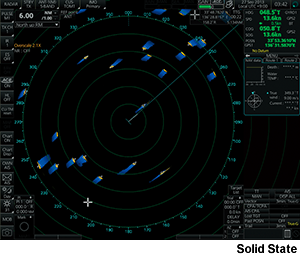
FURUNO’s Solid State Radar technology generates clearer echo images, which allows users to obtain clearer picture of what are around their vessel, including weak targets from small craft.
-
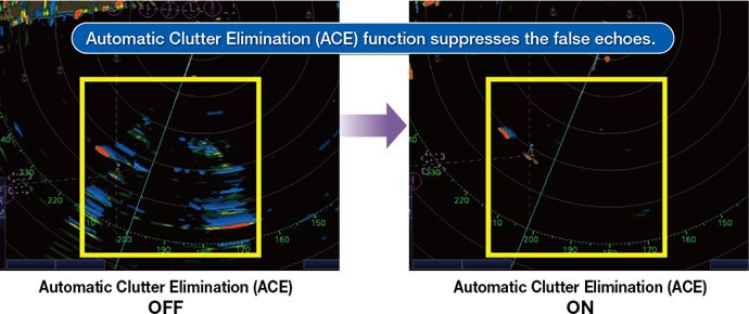
Automatic Clutter Elimination (ACE) function provides clear echoes
Users can quickly adjust the radar image with a single action. When Automatic Clutter Elimination (ACE) function is activated, the system automatically adjusts the clutter reduction filter and gain control according to the sea and weather conditions selected (Calm/Rough Sea/Hard Rain).
Our advanced echo averaging architecture is also incorporated into Automatic Clutter Elimination (ACE) function. Users can avoid complicated adjustment processes, resulting in clear echo images.
-
Improved Target Tracking (TT) function
Target acquisition takes only a few seconds. Acquired target does not jump to adjacent target Reliable and stable tracking of high-speed and rapidly maneuvering vessels
-
Advanced Interference Reduction (IR) function
Target Echo does not become smaller even with IR on
-
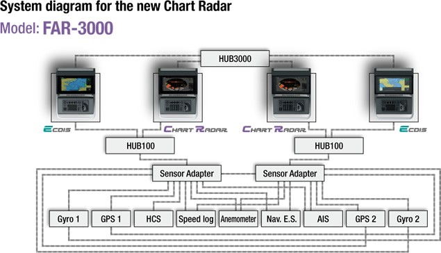
Common sensor adaptor makes installation and maintenance easy
The Sensor Adapter acts as a central medium to gather all of the sensor data and collectively feed it to all FAR-3000 Chart Radar and FMD-3200/3300 ECDIS in the network. Since the sensor adapter can be extended to interface with all the sensors within the network, individual cable connections in the sensor-to-Chart Radar/ECDIS interface can be greatly reduced.
|
Display Unit |
MU-190 |
MU-231 |
MU-270W |
|
Display Type |
19" color LCD |
23.1" color LCD |
27" color wide LCD |
|
Resolution |
SXGA(1280×1024 pixels) |
UXGA(1600×1200 pixels) |
WUXGA (1920x1200 pixels) |
|
PROCESSOR UNIT |
|
| Chart Materials |
IMO/IHO S57 edition-3 ENC vectorized material (IHO S- 63 ENC data protection scheme), C-MAP and CM-93/3 vectorized materials |
| Data Presentation |
Own Ship Target Data(TT: ARPA, AIS) |
| Position Calculation |
Navigation by result from external position sensor Dead reckoning with gyro and log data from gyro, log, and position sensors to be fed to mathmatical filter to generate highly accurate position and speed |
| Navigation Planning |
Planning by rhumb line, great circle |
| Route Monitoring |
Off-track display, waypoint arrival alarm, shallow depth alarm |
| User Chart |
User chart creation and display |
| Notes Data |
Create and display notes data |
| MOB (Man Overboard) |
Position, and other data at time of man overboard are recorded MOB mark is displayed on the screen |
| INTERFACE | |
|
Processor Unit |
|
| DVI |
2 ports, DVI-D (Video signal from DVI-1 and DVI-2 is identical) |
| LAN |
2 ports, Ethernet 1000 Base-T (for Interswitch and Sensor Adapter) |
| USB |
4 ports, USB 2.0 type-A |
| COM |
2 ports, RS232C/RS-485 (for brilliance control) |
| Serial I/O |
8 ports Sentences Input |
| Digital Input |
1 port (for ACK signal input) |
| Contact Closure |
6 ports |
|
Sensor Adapter |
|
| Control and Serial Input |
LAN Serial |
| Analog Input |
3 ports/per unit, -10 to +10 V/0 to 10 V, 4 to 20 mA selectable |
| Digital Input |
8 ports/per unit, normal close or open, selectable |
| Digital Output |
8 ports/per unit, normal close or open, selectable |
|
POWER SUPPLY |
|
| Monitor unit |
MU-270W MU-231 MU-190 |
| Processor unit |
100/230 VAC, 1 phase, 50/60 Hz |
| Power Supply Unit | FAR-3210/3310 FAR-3220/3320/3320W FAR-3220-NXT/3320-NXT FAR-3230S/3330S/3330SW FAR-3230S-SSD/3330S-SSD ( ) : 42 rpm |
ENVIRONMENTAL CONDITIONS
|
Unit |
Ambient Temperature |
Relative Humidity |
Degree of protection |
Vibration |
|
Antenna Unit |
-25°C to +55°C (storage +70°C) |
95? or more at 40°C |
IP56 |
IEC 60945 Ed. 4 |
|
Power Supply Unit |
-15°C to +55°C |
IP20 |
||
|
Processor Unit |
IP20 |
|||
|
Control Unit |
IP22 |
|||
|
Sensor Adapter |
IP22 |
|||
|
Monitor Unit |
IP22 |
ANTENNA UNIT
|
Radiator Type |
XN12CF |
XN20CF |
XN24CF |
SN36CF |
|
Length |
4 ft |
6.5 ft |
8 ft |
12 ft |
|
Frequency |
X band: 9410±30 MHz |
S band: 3050±30 MHz |
||
|
Beamwidth (H) (-3 dB) |
1.9° |
1.23° |
0.95° |
1.8° |
|
Beamwidth (H) (-20 dB) |
4.5° |
2.9° |
2.4° |
4.5° |
|
Beamwidth (V) |
20° |
20° |
20° |
25° |
|
Sidelobe (within ±10°) |
-24 dB |
-28 dB |
-28 dB |
-24 dB |
|
Sidelobe (outside ±10°) |
-30 dB |
-32 dB |
-32 dB |
-30 dB |
TRANSCEIVER UNIT
|
Transceiver Unit |
Magnetron |
||||
|---|---|---|---|---|---|
|
Frequency |
RTR-105 |
RTR-106 |
RTR-108 |
RTR-107 |
RTR-109 |
|
X band: 9410±30 MHz |
S band: 3050±30 MHz |
||||
|
Output Power |
12 kW |
25 kW |
30 kW |
||
|
Transceiver Unit |
Solid State |
|
|
Frequency |
RTR-123 (X band) |
RTR-111 (S band) |
|
P0N: 9403.75 MHz/Q0N: 9423.75 ±5MHz |
P0N: 3043.75 MHz/Q0N: 3063.75±5 MHz |
|
Share: